← Back to Contents
1 Introduction / 1.11 Calibration Procedure | PDF pages 31-54
1.11 Calibration Procedure
1.11 Calibration Procedure
1.11.1 Calibration Procedure
1.11.1.1 Front View Intelligent Camera Calibration Procedure
Objective
• After the vehicle leaves the factory, if it is necessary to perform calibration on the front view intelligent camera again, such as
when the windshield is replaced or the front view intelligent camera is replaced, it is recommended to use the ONL after-sales
calibration procedure.
• The ONL after-sales calibration of the front view intelligent camera is carried out through dynamic driving on the road. The front
view intelligent camera recognizes the lane markings and takes them as a reference to achieve the calibration of the installation
tolerance of the front view intelligent camera.
• If the calibration is not performed after the front view intelligent camera is reinstalled, it will affect the accuracy of image
recognition.
The Following Principles Should Be Followed While Driving
• The vehicle speed should be no less than 22 mph (the recommended vehicle speed is between 22 mph and 35 mph).
• Don't turn the steering wheel by a large margin (||yaw rate|| < 0.008 rad/s).
• Keep driving smoothly before and after changing lanes.
• Don't change lanes frequently.
Requirements For Lanes And Driving Environments
1. The lane on which the vehicle is traveling should be straight and flat, without slopes or turns.
2. Avoid performing calibration in traffic-congested areas and make sure that the lane markings are not blocked by adjacent
vehicles.
3. Avoid performing calibration under adverse weather conditions (such as rain, snow, fog, etc.).
Requirements For The ONL After-Sales Calibration Scenarios Of The front view intelligent camera
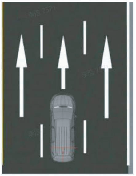
1. The calibration test scenario must include two adjacent lanes of equal width. The lane markings can be either solid lines or
dashed lines, but they should be clearly visible, as shown in the following figure.
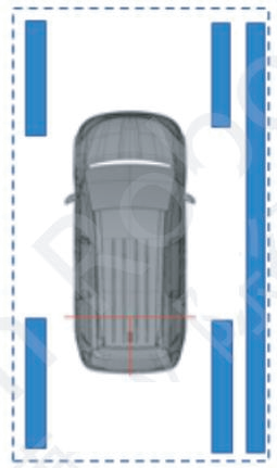
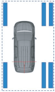
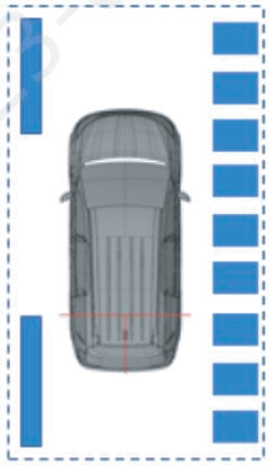
2. Try to avoid the types of lanes shown in the following figure as much as possible.
The ONL After-sales Calibration Process for the front view intelligent camera.
The ONL after-sales calibration can be achieved through the UDS diagnostic service (RoutineControl $31). The host computer
sends diagnostic instructions to the ECU of the front view intelligent camera to trigger the calibration mode. After the calibration
is completed, the parameters will be written into the ECU and will be used after the next power-on.
After the calibration is completed, obtain the calibration results and parameters through diagnostic service instructions as follows:
– The online calibration time of ONL is 1 to 5 minutes, depending on the road conditions.
– It is impossible to exit the ONL mode before the ONL calibration is completed. If the power is turned off during the process, it
will be regarded as a failed end of the ONL calibration, and no new calibration parameters will be written into the ECU.
– There are the following diagnostic service instructions:
1. RoutineControl $31: Send the calibration command (ONL/EOL) under 3212.
2. RoutineControl $31: 3213 Report the current working status (INIT/NORMAL/ONLING/EOLING).
3. RoutineControl $31: 3214 Report the currently used parameters.
4. RoutineControl $31: 3215 Report the new parameters after calibration is completed.
Step 1: Ensure the correct installation of the front view intelligent camera and its covering parts, and check the condition of the
vehicle.
Step 2: Establish communication between the diagnostic device (or calibration computer) and the vehicle. Open the calibration
service through the diagnostic equipment. Click "ONL Calibration" in the diagnostic device and send the calibration instruction
to start the calibration.
Step 3: Drive the vehicle according to the above requirements and complete the automatic calibration function according to the
prompts on the diagnostic device.
Step 4: The diagnostic device prompts "Calibration completed".
Step 5: Return to the ONL mode.
Step 6: The system will automatically write the new calibration parameters into the ECU.
Step 7: Are there any new calibration parameters?
Next step
– Yes:
– No:
The ONL calibration fails.
Step 8: The ONL calibration is successful.
1.11.1.2 Side MMW Radar Calibration Procedure
Preparation for Equipment and Site
• Calibration cloth (3 in front, left, and r
ight).
• Level ground.
• There is no light source that can cause the camera to be exposed by reflection or direct light
Arrangement of Vehicles and Calibration Equipment
Park the vehicle on calibration site and adjust the calibration cloth as required.
6
7
1
5
4
8
9
3
• ①Distance between front calibration cloth and vehicle: 1.6 ft
• ⑥Lateral distance of front calibration cloth: 21.6 ft
• ⑦Longitudinal distance of front calibration cloth: 5.9 ft
• ⑤Distance between front calibration cloth and left/right calibration cloth: 4.9 ft
• ⑧Width of left/right calibration cloth: 5.9 ft
• ⑨Length of left/right calibration cloth: 7.9 ft
• ④Distance from left/right calibration cloth: 9.8 ft
Note
The black grid on the three pieces of cloth is a square of edge length 1 ft. Align the edges (or the white edges of
equal width) of the outermost black grids when aligning the cloth; A white edge of width 0.5 ft should be reserved at
the edge of the three calibration cloths.
Precautions
1. Make sure the calibration patterns are visible through the camera and the position requirements stipulated in the calibration
scheme are met;
2. The site should be free of reflections. If the photo is not clear due to reflection, use shielding cloth or shade to ensure that the
black and white grids are clear;
3. If the calibration fails, export the corresponding photos and logs and send them to the manufacturer for analysis;
Calibration Procedure
1. On the CAR screen, go to the home page: My Weidu;
2. Select Version Information, long-press the IPC version number, enter the password in the pop-up window: Yaxon@weidu11 to
access the backend configuration;
3. Tap General Host Settings Parameters;
4. In the IVI screen pop-up, select the 270 debug screen switch.
5. Click AVM icon on the main interface of the CAR screen to activate AVM;
6. When clicking "Calibration" button, the automatic calibration will start. You can wait for the automatic calibration to end, or
manually click "End Calibration" to stop the current calibration;
7. When the calibration process (including calibration succeeded, calibration failed, and manual stop of calibration) ends, you
should operate "Turn Off AVM", "Turn On AVM", and "Initialize AVM" to display the screen again. Then you can operate
"Calibration" again according to the process same as step 1;
8. It is determined that the calibration is successfully if the 2D/3D function can be used normally, the splicing accuracy meets the
requirements, and the calibration cloth is not misplaced from the perspective of the screen;
9. Click "Hide Debug" button to collapse the control bar, and click this button again to expand it. Prevent the debug button from
blocking the picture and affecting the observation;
10. Click "Close Debug Interface" to exit the calibration interface, or re-enter the factory settings interface to open it;
11. Click "Collect Fusion Image" to collect the AVM fusion image (including the car model);
12. Click "Collect Left Image" to collect the left image, save it to path /sdcard/AvmDataCollect/LeftImage, and name it "cameraId"
+ "_id_Image_" + "Current System Boot Timestamp" + "Serial Number".
13. Click "Collect Front Image" to collect the front image, save it to path /sdcard/AvmDataCollect/FrontImage, and name it
"cameraId" + "_id_Image_" + "Current System Boot Timestamp" + "Serial Number".
14. Click "Collect Right Image" to collect the right image, save it to path /sdcard/AvmDataCollect/RightImage, and name it
"cameraId" + "_id_Image_" + "Current System Boot Timestamp" + "Serial Number".
15. Click "Collect Back Image" to collect the back image, save it to path /sdcard/AvmDataCollect/BackImage, and name it
"cameraId" + "_id_Image_" + "Current System Boot Timestamp" + "Serial Number".
16. Click "Collect Four-way Image" to collect the left, front, right, and back images simultaneously, save them in respective
directory, and name them "special_" + "cameraId" + "_id_Image_frame_" + "Serial Number" beginning with "special_";
For example:
• Rear view: special_0_id_Image_frame_1.yuyv
• Right view: special_5_id_Image_frame_1.yuyv
• Front view: special_7_id_Image_frame_1.yuyv
• Left view: special_8_id_Image_frame_1.yuyv
cameraId mapping rules:
• cameraId =0 refers to AVM back image
• cameraId =5 refers to AVM right image
• cameraId =7 refers to AVM front image
• cameraId =8 refers to AVM left image
Exporting Image Collection Footage
You can export or clear the footage by unzipping the "Attachment Script" file and executing the corresponding script.
Note
Select a practical dual male USB cable, and insert one end into the USB flash drive socket of the device host, and
the other end into the computer. Concurrently, switch the current mode to ADB. Otherwise, the script cannot be
executed normally.
Exporting steps:
Click "Export AVM Collection Footage" in "AVM Image Collection Export Script" to export the file.
Click "Clear AVM Collection Footage" in "AVM Image Collection Export Script" to clear the export file.
1.11.1.3 Forward MMW Radar Calibration Procedure
Preparation for Equipment and Site
– Tools: 10# hexagon socket and 8# hexagon socket, with a total length not exceeding 150mm.
– Tape measure or laser rangefinder (electronic ruler).
– Site: Dark site where the ground is level and flat, vehicles can enter, and the reference center of the headlamp is be at least
10m away from the
screen.
– Test screen: Thick white paper or white wall (in order to facilitate the observation of light shape, the test screen shall be more
than 2m wider than the vehicle).
Vehicle Preparation
– Inflate the tire in accordance with the full load pressure specified in the technical conditions of the vehicle.
– After the vehicle ECAS calibration is completed, set the suspension height to "Standard" in the "Control Center-Setting-
ECAS Adjustment" section on the CAR screen.
– Replenish sufficient water and lubricating oil on the vehicle, and prepare all accessories and tools (spare tires, tools, etc.) for
vehicle test.
– Place a 75kg load on driver seat to simulate driver seat occupation.
– Before measuring, make sure the vehicle is at natural standstill state, drive the vehicle to travel backwards for at least one
wheel circumference and then forward over the same distance.
– Make sure the outer cover of the lamps is clean.
– Start the vehicle.
Light Measurement
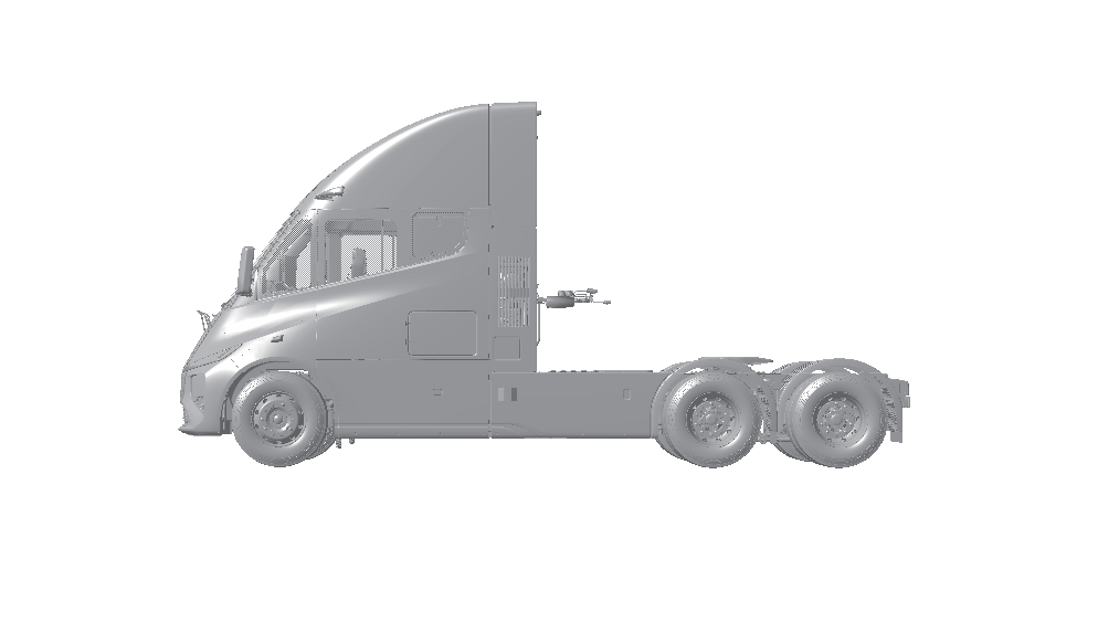
1. Park the vehicle as shown in the figure with the distance L between the reference center of the headlamp and the screen being
10m.
h 1
h2
2. Remove the wheel housing plug.

3. Draw O-line, A-line, and B-line on the screen.
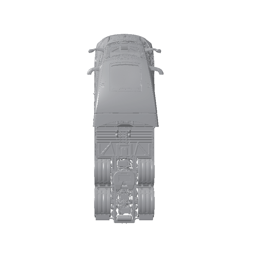
L1
90°
L1
– A and B lines: Parallel to O line, where L1 is 39.5 in (low beam) or 40.25 in (high beam).
4. Draw A1, A2, B1, B2, h1, and h2 lines on the screen to form a green box as shown in the figure after completing drawing of all
lines.
a1
a2
b1
b2
L2
L3
L4
L5
h1
h2
• A1 and A2 lines: Parallel to line A, where L2 is 6.69 in and L3 is 13.75 in;
• B1 and B2 lines: Parallel to line B, where L4 is 6.69 in and L5 is 13.75 in;
• H1 and H2 lines: Horizontal lines parallel to the ground, where H1 is 33.7 in (low beam) or 35.55 in (high beam), and H2 is
23.86 in (low beam) or 25.28 in (high beam).
Light Adjustment
caution
To make it easier to observe the effect of light adjustment, you can block the light from one side side when adjusting
the light on the other side. The light adjustment method on the left and right sides is the same. After the debugging is
completed, the height of the left and right lights should be consistent.
Note
The left headlamp is taken as an example hereby. The light adjustment method of the left headlamp is the same as
that of the right headlamp.
1. Low beam adjustment
1. Turn on the low beam.
2. Insert the 10# hexagon socket into the low beam dimming port ①, rotate the handle ①clockwise to adjust the light to the
upper left, and turn the handle ①counterclockwise to adjust the light to the lower right; Insert the 8# hexagon socket into the
low beam dimming port ②, rotate the handle ②clockwise to adjust the light downward, and turn the handle ②
counterclockwise to adjust the light upward;
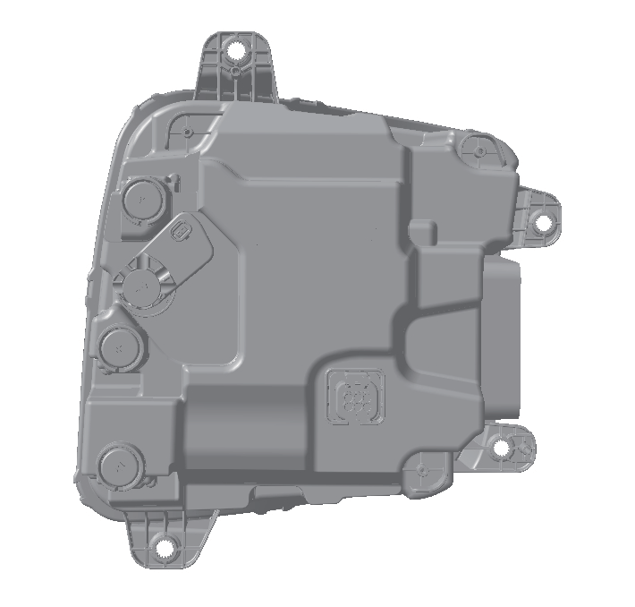
1
2
3. If the turning point of the low beam cut-off line is in the frame, it indicates the completion of dimming.

2. High beam adjustment
1. Turn on the high beam;
2. Insert the 10# hexagon socket into the high beam dimming port ③, rotate the handle ③clockwise to adjust the light to the
upper left, and turn the handle ③counterclockwise to adjust the light to the lower right; Insert the 10# hexagon socket into the
higih beam dimming port ④, rotate the handle ④clockwise to adjust the light downward, and turn the handle ④
counterclockwise to adjust the light upward;
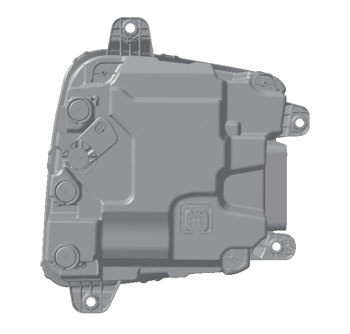
3
4
3. If the brightest point of the high beam is in the frame, it indicates the completion of dimming.
caution
After the adjustment of the high and low beams is completed, the brightest point of the high beam should be
higher than the turning point of the low beam cut-off line.
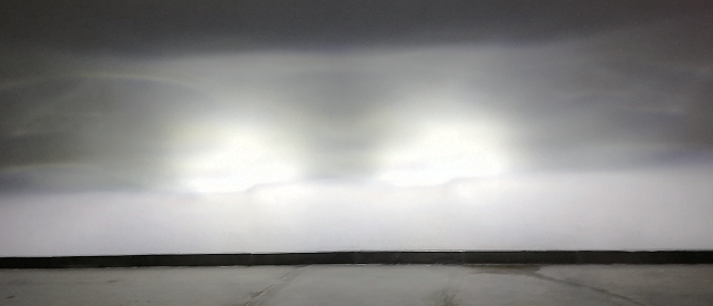
1.11.1.4 270-degree panoramic calibration
Operation Process
Step 1: Check if the vehicle meets the following
conditions?
– Vehicle status is READY
– Brake opening is 0
– Throttle opening is 0
– Handbrake pulled up
Next step
-Yes:
Adjust vehicle status.
-No:
Step 2: Connect the diagnostic instrument and click on the "TCU self-learning instruction".
Step 3: axle self-learning in TCU1.
Step 4: 1-file self-learning.
Step 5: Is the target gear met?
Next step
-Yes:
After restarting the vehicle power-on operation, perform the self-learning process again. If it fails after three
attempts, report the fault and exit the self-learning program.
-No:
Step 6: Explore the tolerance position and record the actual position.
Step 7: 2-file self-learning.
Step 8: Is the target gear met?
Next step
-Yes:
After restarting the vehicle power-on operation, perform the self-learning process again. If it fails after three
attempts, report the fault and exit the self-learning program.
-No:
Step 9: Explore the tolerance position and record the actual position.
Step 10: Gear position check.
Step 11: Parameters are written to EEPROM.
Step 12: Send the self-learning completion flag.
Step 13: End of self-learning.
Step 14: TCU2 rear axle self-learning.
Step 15: 1 file self-learning.
Step 16: Is the target gear satisfied?
Next step
-Yes:
After restarting the vehicle power-on operation, perform the self-learning process again. If it fails after three
attempts, report the fault and exit the self-learning program.
-No:
Step 17: Explore the tolerance position and record the actual position.
Step 18: 2-file self-learning.
Step 19: Is the target gear met?
Next step
-Yes:
After restarting the vehicle power-on operation, perform the self-learning process again. If it fails after three
attempts, report the fault and exit the self-learning program.
-No:
Step 20: Explore the tolerance position and record the actual position.
Step 21: Gear position check.
Step 22: Parameters are written to the EEPROM.
Step 23: Send the self-learning completion flag.
Step 24: End of self-learning.
1.11.1.5 Headlamp Light Adjustment
Introduction to Preparation of Calibration Tools and Related Functions
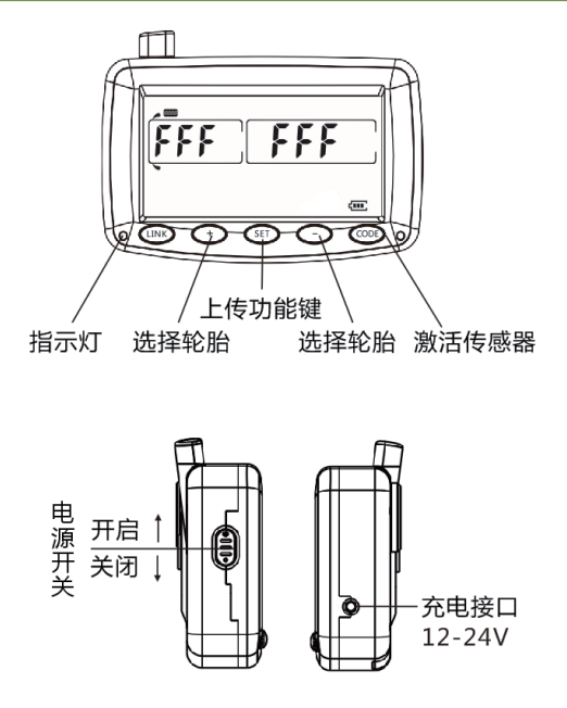
6
7
5
1
2
4
3
– ①: Indicator
– ②: Select tires
– ③: Upload function button
– ④: Select tires
– ⑤: Activate the sensor
– ⑥: Power switch
– ⑦: 12–24V charging interface
Description of Buttons on Calibration Tool
On/off: Turn the switch on the left to turn on the tool. The calibration tool goes into screen off and sleeping state if there is no
operation within 3 minutes after power-on. Press any button to wake up the calibration tool.
Setting Standard Pressure (Note: Confirm Standard Tire Pressure Before Individual Operations, standard pressure
is input by the chassis according to the tire type.)
1. Press and hold the LINK button on the left, press upward the power button on the left to turn on the tool, go into the interface
for adjusting the standard pressure value, and press the "+" or "-" button according to the actual pressure standard to adjust.
After the adjustment is completed, press and hold the LINK button for 3 seconds to save and return to the main interface.
2. After setting of the calibration tool is completed, power on the vehicle, walk to the right rear tire position of the vehicle (near the
installation position of the tire pressure CAN module host), press and hold the SET button in the middle of the device for two
seconds and upload information to the tire pressure CAN module host.
Sensor Detection Operation
1. Walk to the tire and press the "CODE" button on the rightmost of the calibration tool to enter the detection mode, and the
display will show "Id LF"; Place the display of the calibration tool close to the tire sensor (generally near the valve, with the
calibration tool be kept no more than 7.87 in from the tire); After reading the code, a long "Be" sound will be heard and the tire
data will be shown: The six-digit ID code, temperature and pressure display in turn.
2. When the code reading fails, a short "Be-Be" sound will be heard with "Id Err" displayed, and then the screen will automatically
return to standby state. In this case, you can readjust the position and reactivate.
Instructions for Calibration
1. Walk to the tire and press "+" button on the calibration tool to select the corresponding tire position. Concurrently, press the
"CODE" button on the rightmost of the calibration tool to enter the code matching mode with "Id LF" displayed on the screen;
Place the display of the calibration tool close to the tire sensor (generally near the valve, with the calibration tool be kept no
more than 7.87 in from the tire); After reading the code, a long "Be" sound will be heard and the tire data will be shown: ID
code, pressure and temperature under normal conditions, with black dots appeared on the corresponding position of the tire. If
code reading is successful, continue to press the "+" button to select the corresponding tire position for the purpose of
activating the sensor.
caution
There are 10 tires in total. Thus you should make sure data showing black dots on 10 tires is shown on the
calibration tool. Considering that crosstalk is easy to occur in side-by-side tires after the sensor is activated, you
should manually insert the equipment into the inner tube as far as possible when activating the inside tire and
keep as far away as possible from the outer valve (7.87 in - 15.74 in) when activating the outside tire.
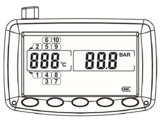
Corresponding number
Vehicle location
1 (driver seat)
Left side of input shaft
Right side of input shaft
2
Left outside of output shaft
3
Corresponding number
Vehicle location
Left inside of output shaft
4
Right inside of output shaft
5
Right outside of third shaft
6
7
Left outside of third shaft
8
Left inside of third shaft
Right inside of third shaft
9
Right outside of third shaft
10
2. When the code reading fails, a short "Be-Be" sound will be heard with "Id Err" displayed, and then the screen will automatically
return to standby state.
Uploading Data Read by Calibration Tool to CAN-based Tire Pressure Host
Locate the tire pressure CAN receiver installed on the vehicle (the host is near the inside of the right rear tire), stand on the right
rear tire and press the middle upload button "SET" (about 1 second), and the calibration tool will upload the entire set of tire data
to CAN receiver. The LCD flashes during the upload process, and after the uploading is completed, the calibration tool will
display FINISH, and you can Check the tire pressure data on the instrument panel is updated.
caution
Make sure the data showing black dots on 10 tires is shown on the calibration tool. 8.3BAR=120 psi means that the
current standard pressure is set to 120 psi.
1.11.1.6 TCU Self-Learning Program
Yaw Rate Sensor Calibration Scene
• Replace the slew rate sensor
.
• Replace the EBS ECU.
Vehicle Calibration Requirements
• Keep the wheels straight.
Calibration Procedure
Step 1: Perform vehicle power-on operations.
Step 2: Connect the scan tool to the DLC.
Step 3: Automatically identify or select Windrose - Select corresponding model - Click the special function - Calibrate yaw rate
on the scan tool.
Step 4: Operate following the prompts on the scan tool interface.
Step 5: Calibration is completed.
1.11.1.7 Tire Pressure Calibration Procedure
Steering Angle Sensor Calibration Scene
• Replace the steering angle sensor
.
• Replace the EBS ECU.
Vehicle Calibration Requirements
• Keep the wheels straight.
Calibration Procedure
Step 1: Perform vehicle power-on operations.
Step 2: Connect the scan tool to the DLC.
Step 3: Automatically identify or select Windrose - Select corresponding model - Click the special function - Calibrate steering
angle on the scan tool.
Step 4: Operate following the prompts on the scan tool interface.
Step 5: Calibration is completed.
1.11.1.8 Yaw Rate Sensor Calibration Procedure
EPB Angle Zeroing Scene
• Replace the parking solenoid valve.
Vehicle Calibration
Requirements
• The vehicle should be parked on level road.
Calibration Procedure
Step 1: Perform vehicle power-on operations.
Step 2: Connect the scan tool to the DLC.
Step 3: Automatically identify or select Windrose on the scan tool - Select corresponding model - Click the special function -
Angle zeroing.
Step 4: Operate following the prompts on the scan tool interface.
Step 5: Calibration is completed.
1.11.1.9 Steering Angle Sensor Calibration Procedure
Calibration Device
– Computer: Laptop running with WIN7 or higher operating system;
– CAN adapter: Special USB-CAN adapter
Connect the USB port of the computer and the OBD port of the vehicle through the adapter and adapter cable to communicate
with ECAS ECU. The adapter cable is designed with three DB9 adapters that are compatible with CAN cables. Select
appropriate adapters with adapter 9-pin interfaces according to the CAN pin definition of the OBD on real vehicles.
Function of ECAS Calibration Software
– Upon completion of installation of the ECAS, calibrate its initial height, including the normal height, the height upper limit
and
the height lower limit;
– Diagnose faults; Modify ECU parameter configuration;
– The auxiliary detection of ECAS EOL covers detection of ECAS solenoid valve movement, detection of height sensor
installation and detection of signal, etc.
Software Startup
Connect the computer to ECU via a diagnostic cable, turn on the main power and key power, and then run the calibration
software.
Software Main Interface
After the software is successfully connected to the ECAS ECU, you can read the power supply voltage, software version, fault
information, etc. on the interface.
Parameter Configuration
Options: Modify Individual Parameters or Modify All Parameters are available as needed. The parameter value determines the
structure configuration and function settings of ECAS. The parameters can be exported from the prototype or pre-documented
and imported into a new ECU during configuration. Parameter configuration should be completed by specially trained calibrators.
Modification of Individual Parameters
1. Click "System" menu to select "Parameters", or directly click the button icon in the shortcut bar to enter the parameter
configuration interface.
2. Click "Read From ECU" button to read current parameters in ECU and check the current value of the specified parameter. To
modify the value of the specified parameter, you can directly enter the value in the blank of "Parameter Value", and then click
"Write Into ECU" button. You will be prompted to enter a verification code during writing (the last four characters of ROOT code
when registering the license).
Modification of All Parameters
You can import or export all ECU parameters via "ECU Replacement" function. In addition to the general parameters displayed
on "Parameter Interface", CAN bus configuration, axle load information, default height characteristic parameters, etc. are
included. Data bulk load or exporting calibration data for backup can be achieved through "ECU Replacement". After importing,
click "ECU Reset" on the shortcut button bar to allow parameters to come into effect. You will be prompted to enter a verification
code during importing.
Fault Inspection
Upon completion of parameter configuration and ECU reset, wait for more than 8 seconds to observe the calibration software
interface and check if there is a fault prompt.
If a fault occurs, determine the type of fault according to the current fault information read through the calibration software, and
eliminate the fault step by step.
After troubleshooting, click "ECU Reset", wait for more than 8 seconds again, and confirm that there is no DTC before
proceeding to the next step for detection of solenoid valve and height sensor as well as height calibration.
Solenoid Valve and Sensor Control Detection
caution
The chassis may suddenly go up and down during lifting test and calibration. Thus, in this process, make sure the
installation personnel is in a safe position!!!
Run the ECAS calibration software, click the "System" menu after successful connection, and select "Inflate/Deflate Solenoid
Valve" to enter the detection interface.
Select the installed airbag for testing. Operation method: Select the front axle airbag, left rear airbag, right rear airbag and other
airbags separately on the interface, and click Inflate or Deflate to observe the shape and pressure change of the corresponding
airbag are correct, and Check the solenoid valve channels are normal and whether the left and right pipelines are falsely
connected. Check the air pressure value is normal and whether the connectors of the air pressure sensor (if any) are connected
correctly.
During inflation or deflation of the solenoid valve, observe the value of height sensor changes towards the correct direction and
Check the height sensor is reversed while the chassis is rising or lowering;
caution
Calibrate "Lifting test" function of software. It disables the solenoid valve automatically when failed to prevent
damages to the circuit as a result of short circuit.
Height Sensor Misconnection Detection
caution
The chassis may suddenly go up and down during lifting test and calibration. Thus, in this process, make sure the
installation personnel is in a safe position!!!
Unplug the height sensor and observe the fault information on the main interface of the calibration software is correct. For
example, after unplugging the left rear height sensor, refresh the main interface to see if the corresponding DTC appears in
"Current Fault" window. (For ECAS with height sensors mounted on the left and right sides of the rear axle)
caution
Lock the vehicle during diagnosis of ECAS!
Automatic control and regulation may occur in ECAS during the diagnosis, causing sudden movement of the vehicle.
Height Calibration
caution
The chassis may suddenly go up and down during lifting test and calibration. Thus, in this process, make sure the
installation personnel is in a safe position!!!
Principle of height calibration:
– Before calibration, park the vehicle with normal tire pressure on level ground.
– The calibration is generally performed on unloaded vehicle, making it difficult to descend during calibration. For this reason,
it is necessary to release the handbrake once, or calibrate with the vehicle loaded.
– After the calibration is completed, difference in the air pressure of the left and right airbags may be detected or even the
unilateral airbag may be collapsed on the unloaded vehicle following road test and movement. This is generally attributed to the
distribution error of left and right weight on the suspension. It returns to normal if the air pressure in left and right airbags is close
after vehicle loading.
– In addition, the difference in left and right air pressure may be present after the running-in of the vehicle. If the difference
remains significant after loading, re-correct the zero point of the swing rod, or re-calibrate as necessary.
Height calibration process:
1. Select "Calibrate Height Sensor" option: In the shortcut menu bar on the main interface, click shortcut button of "Calibrate
Height Sensor" to enter the calibration. Two calibration methods are available: three-point height calibration (normal height,
upper limit height and lower limit height calibration) and single-point height calibration (limited to normal height calibration;
upper limit height and lower limit height are automatically calculated and written by calibration software on the basis of a new
normal height according to the default upper and lower limit offset in ECU).
2. : Select the airbag to be adjusted, inflate and deflate it to normal height: After adjusting the airbag to normal position, visually
check that the swing rod is level, and confirm the height value (2nd generation sensor: 270-330TT; 1st generation sensor 190-
240TT). No specific requirements are imposed on the difference in left and right height values. Make sure the difference is not
more than 20TTwhen the swing rod maintains level through visual inspection.
caution
When two height sensors are available, the height adjustment on left and right must be selected simultaneously.
After the swing rod is leveled, fix it, and click to save the normal height. (When single-point calibration is selected,
the upper limit and lower limit calibration will be automatically completed; When three-point calibration is selected,
after the normal height is saved, you should raise the suspension to maximum height and save the upper limit
height, and then lower the suspension to the minimum height and save the upper limit and lower limit height)
3. Fill in the real height value of chassis or airbag: If the automobile factory makes a request for writing the real current normal
height, upper limit height, and lower limit height simultaneously when saving the height, you should fill in the corresponding
height value (mm) in the pop-up window for filling. This function is only available in V1.3.2.5 and above version calibration
software.
4. Click "End Calibration" to exit the calibration process. Click "ECU Reset" button in the shortcut menu bar to allow the new
height to come into effect.
1.11.1.11 ECAS Calibration Procedure
Diagnosis Procedure
Step 1: Perform vehicle power-on operations.
Step 2: Connect the scan tool to the DLC.
Step 3: Click "Traditional Diagnosis" in scan tool.
Step 4: Select the corresponding Windrose vehicle in scan tool.
Step 5: Check the VIN identified by the scan tool in the interface is consistent with the vehicle
model?
Next step
— Yes:
Manually enter the VIN
— No:
Step 6: Click OK following the prompts on the interface of the scan tool.
Step 7: Select "System Topology" on the interface of the scan tool.
Step 8: Click "BDCU" on the interface of the scan tool.
Step 9: Select "Special Function".
Step 10: Codes, reset, relearning and other special options will be displayed on the interface of the scan tool.
Step 11: Learn from the actual scenes of "BDCU" repair or replacement.
Step 12: End.
1.11.1.11 ECAS Calibration Procedure
Diagnosis Procedure
Step 1: Perform vehicle power-on operations.
Step 2: Connect the scan tool to the DLC.
Step 3: Click "Traditional Diagnosis" in scan tool.
Step 4: Select the corresponding Windrose vehicle in scan tool.
Step 5: Check the VIN identified by the scan tool in the interface is consistent with the vehicle
model?
Next step
— Yes:
Manually enter the VIN
— No:
Step 6: Click OK following the prompts on the interface of the scan tool.
Step 7: Select "System Topology" on the interface of the scan tool.
Step 8: Click "CDC" on the interface of the scan tool.
Step 9: Select "Special Function".
Step 10: Codes, reset, relearning and other special options will be displayed on the interface of the scan tool.
Step 11: Learn from the actual scenes of "CDC" repair or replacement.
Step 12: End.
1.11.1.12 BDCU Software Diagnosis Procedure
Diagnosis Procedure
Step 1: Perform vehicle power-on operations.
Step 2: Connect the scan tool to the DLC.
Step 3: Click "Traditional Diagnosis" in scan tool.
Step 4: Select the corresponding Windrose vehicle in scan tool.
Step 5: Check the VIN identified by the scan tool in the interface is consistent with the vehicle
model?
Next step
— Yes:
Manually enter the VIN
— No:
Step 6: Click OK following the prompts on the interface of the scan tool.
Step 7: Select "System Topology" on the interface of the scan tool.
Step 8: Click "CMU1" on the interface of the scan tool.
Step 9: Select "Special Function".
Step 10: Codes, reset, relearning and other special options will be displayed on the interface of the scan tool.
Step 11: Learn from the actual scenes of "CMU1" repair or replacement.
Step 12: End.
1.11.1.13 CDC Software Diagnosis Procedure
Diagnosis Procedure
Step 1: Perform vehicle power-on operations.
Step 2: Connect the scan tool to the DLC.
Step 3: Click "Traditional Diagnosis" in scan tool.
Step 4: Select the corresponding Windrose vehicle in scan tool.
Step 5: Check the VIN identified by the scan tool in the interface is consistent with the vehicle
model?
Next step
— Yes:
Manually enter the VIN
— No:
Step 6: Click OK following the prompts on the interface of the scan tool.
Step 7: Select "System Topology" on the interface of the scan tool.
Step 8: Click "CMU2" on the interface of the scan tool.
Step 9: Select "Special Function".
Step 10: Codes, reset, relearning and other special options will be displayed on the interface of the scan tool.
Step 11: Learn from the actual scenes of "CMU2" repair or replacement.
Step 12: End.
1.11.1.14 CMU1 Software Diagnosis Procedures
Diagnosis Procedure
Step 1: Perform vehicle power-on operations.
Step 2: Connect the scan tool to the DLC.
Step 3: Click "Traditional Diagnosis" in scan
tool.
Step 4: Select the corresponding Windrose vehicle in scan tool.
Step 5: Check the VIN identified by the scan tool in the interface is consistent with the vehicle model?
Next step
— Yes:
Manually enter the VIN
— No:
Step 6: Click OK following the prompts on the interface of the scan tool.
Step 7: Select "System Topology" on the interface of the scan tool.
Step 8: Click "CMU3" on the interface of the scan tool.
Step 9: Select "Special Function".
Step 10: Codes, reset, relearning and other special options will be displayed on the interface of the scan tool.
Step 11: Learn from the actual scenes of "CMU3" repair or replacement.
Step 12: End.
1.11.1.15 CMU2 Software Diagnosis Procedures
Diagnosis Procedure
Step 1: Perform vehicle power-on operations.
Step 2: Connect the scan tool to the DLC.
Step 3: Click "Traditional Diagnosis" in scan tool.
Step 4: Select the corresponding Windrose vehicle in scan tool.
Step 5: Check the VIN identified by the scan tool in the interface is consistent with the vehicle
model?
Next step
— Yes:
Manually enter the VIN
— No:
Step 6: Click OK following the prompts on the interface of the scan tool.
Step 7: Select "System Topology" on the interface of the scan tool.
Step 8: Click "CMU4" on the interface of the scan tool.
Step 9: Select "Special Function".
Step 10: Codes, reset, relearning and other special options will be displayed on the interface of the scan tool.
Step 11: Learn from the actual scenes of "CMU4" repair or replacement.
Step 12: End.
1.11.1.16 CMU3 Software Diagnosis Procedures
Diagnosis Procedure
Step 1: Perform vehicle power-on operations.
Step 2: Connect the scan tool to the DLC.
Step 3: Click "Traditional Diagnosis" in scan tool.
Step 4: Select the corresponding Windrose vehicle in scan tool.
Step 5: Check the VIN identified by the scan tool in the interface is consistent with the vehicle
model?
Next step
— Yes:
Manually enter the VIN
— No:
Step 6: Click OK following the prompts on the interface of the scan tool.
Step 7: Select "System Topology" on the interface of the scan tool.
Step 8: Click "HUD" on the interface of the scan tool.
Step 9: Select "Special Function".
Step 10: Codes, reset, relearning and other special options will be displayed on the interface of the scan tool.
Step 11: Learn from the actual scenes of "HUD" repair or replacement.
Step 12: End.
1.11.1.17 CMU4 Software Diagnosis Procedures
Diagnosis Procedure
Step 1: Perform vehicle power-on operations.
Step 2: Connect the scan tool to the DLC.
Step 3: Click "Traditional Diagnosis" in scan tool.
Step 4: Select the corresponding Windrose vehicle in scan tool.
Step 5: Check the VIN identified by the scan tool in the interface is consistent with the vehicle
model?
Next step
— Yes:
Manually enter the VIN
— No:
Step 6: Click OK following the prompts on the interface of the scan tool.
Step 7: Select "System Topology" on the interface of the scan tool.
Step 8: Click "IPC" on the interface of the scan tool.
Step 9: Select "Special Function".
Step 10: Codes, reset, relearning and other special options will be displayed on the interface of the scan tool.
Step 11: Learn from the actual scenes of "IPC" repair or replacement.
Step 12: End.
1.11.1.18 HUD Software Diagnosis Procedure
Diagnosis Procedure
Step 1: Perform vehicle power-on operations.
Step 2: Connect the scan tool to the DLC.
Step 3: Click "Traditional Diagnosis" in scan tool.
Step 4: Select the corresponding Windrose vehicle in scan tool.
Step 5: Check the VIN identified by the scan tool in the interface is consistent with the vehicle
model?
Next step
— Yes:
Manually enter the VIN
— No:
Step 6: Click OK following the prompts on the interface of the scan tool.
Step 7: Select "System Topology" on the interface of the scan tool.
Step 8: Click "SSM" on the interface of the scan tool.
Step 9: Select "Special Function".
Step 10: Codes, reset, relearning and other special options will be displayed on the interface of the scan tool.
Step 11: Learn from the actual scenes of "SSM" repair or replacement.
Step 12: End.
1.11.1.19 IPC Software Diagnosis Procedure
Diagnosis Procedure
Step 1: Perform vehicle power-on operations.
Step 2: Connect the scan tool to the DLC.
Step 3: Click "Traditional Diagnosis" in scan tool.
Step 4: Select the corresponding Windrose vehicle in scan tool.
Step 5: Check the VIN identified by the scan tool in the interface is consistent with the vehicle
model?
Next step
— Yes:
Manually enter the VIN
— No:
Step 6: Click OK following the prompts on the interface of the scan tool.
Step 7: Select "System Topology" on the interface of the scan tool.
Step 8: Click "TPMS" on the interface of the scan tool.
Step 9: Select "Special Function".
Step 10: Codes, reset, relearning and other special options will be displayed on the interface of the scan tool.
Step 11: Learn from the actual scenes of "TPMS" repair or replacement.
Step 12: End.
1.11.1.20 SSM Software Diagnosis Procedure
Diagnosis Procedure
Step 1: Perform vehicle power-on operations.
Step 2: Connect the scan tool to the DLC.
Step 3: Click "Traditional Diagnosis" in scan tool.
Step 4: Select the corresponding Windrose vehicle in scan tool.
Step 5: Check the VIN identified by the scan tool in the interface is consistent with the vehicle
model?
Next step
— Yes:
Manually enter the VIN
— No:
Step 6: Click OK following the prompts on the interface of the scan tool.
Step 7: Select "System Topology" on the interface of the scan tool.
Step 8: Click "AC" on the interface of the scan tool.
Step 9: Select "Special Function".
Step 10: Codes, reset, relearning and other special options will be displayed on the interface of the scan tool.
Step 11: Learn from the actual scenes of "AC" repair or replacement.
Step 12: End.
1.11.1.21 TPMS Software Diagnosis Procedure
Diagnosis Procedure
Step 1: Perform vehicle power-on operations.
Step 2: Connect the scan tool to the DLC.
Step 3: Click "Traditional Diagnosis" in scan tool.
Step 4: Select the corresponding Windrose vehicle in scan tool.
Step 5: Check the VIN identified by the scan tool in the interface is consistent with the vehicle
model?
Next step
— Yes:
Manually enter the VIN
— No:
Step 6: Click OK following the prompts on the interface of the scan tool.
Step 7: Select "System Topology" on the interface of the scan tool.
Step 8: Click "VDC" on the interface of the scan tool.
Step 9: Select "Special Function".
Step 10: Codes, reset, relearning and other special options will be displayed on the interface of the scan tool.
Step 11: Learn from the actual scenes of "VDC" repair or replacement.
Step 12: End.