Windrose High-Voltage Safety Operating Guide
This is the unified guide. The shorter step-by-step page is still available: High-voltage power-down and voltage check. Only English is available for now.
Version 1, 22 November 2026. Merged from four Windrose sources. Only steps and values found in those sources are included; nothing was added. Applies to Windrose E700 / WH13 (the sources state that the content applies to all markets).
Terminology: this guide uses one term throughout: "service disconnect (MSD)". It is the low-voltage plug that makes the truck switch off the high voltage when pulled. The sources also call it "low-voltage service disconnect", "low-voltage maintenance power-off plug" or "low voltage MSD".
Source codes
- A = windrose.ai "How to work safely" page (high-voltage-safety), reached from how-to-service. It quotes service manual 1.9 and chapter 4.
- B = WH13 Diagnostic and Repair Manual 1.9 "Power Down of the High-Voltage System" (public version), and the manual sections 4.3, 4.6 and 7.4 for figures.
- C = Owner Manual (US): 9.J High-Voltage Safety Maintenance (9.J.1 principles, 9.J.2 personnel, 9.J.3 maintenance, 9.J.4 charging maintenance), plus 8.I, 8.K and 6.D.1.
- D = windrose.ai/recovery: Emergency Response / Rescue Guide WINDROSE-202408-001 (Version 01) and the towing / recovery / transportation / storage guide.
Note to the reader: the "10 minutes", "three readings below 60 V" and "lock-out / tag-out" requirements appear only in source A. The text of manual 1.9 (B) does not contain them.
1 Scope and personnel qualification
Source: C 9.J.1–9.J.3, A, D
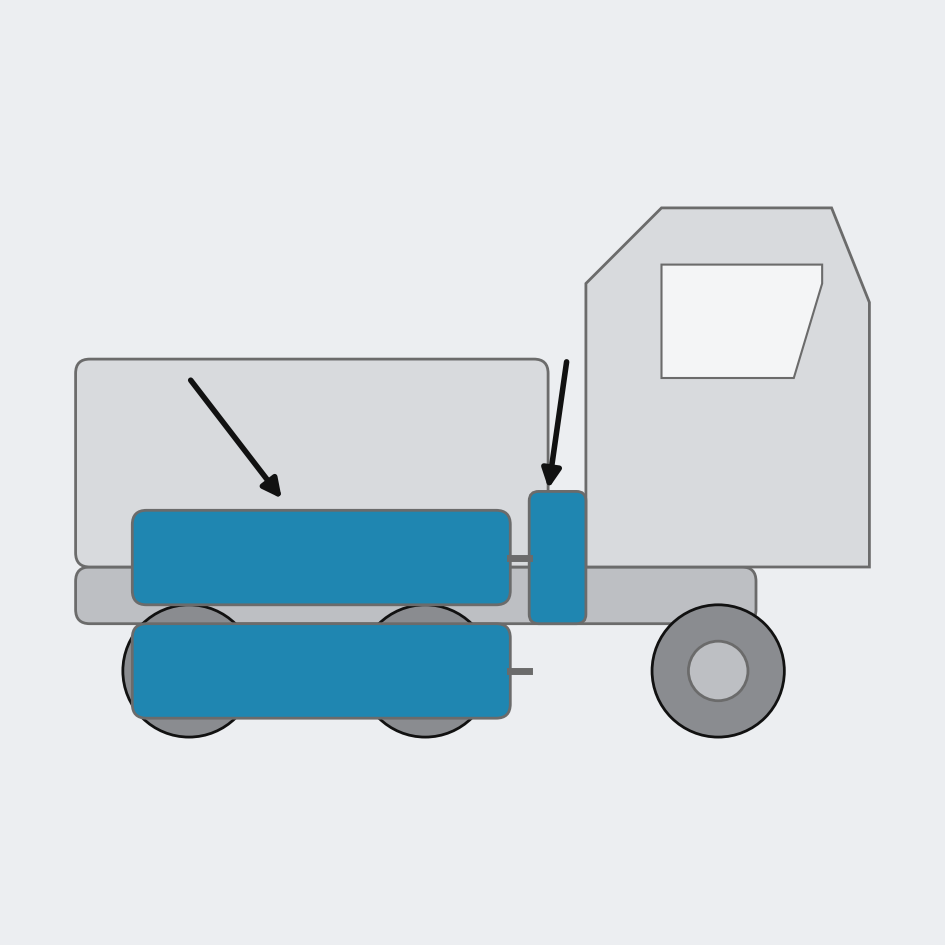 |
- This guide applies to power-down, checking, repair and power-up of the high-voltage (HV) system of Windrose electric trucks, and to emergency handling after an incident.
- Only technicians with high-voltage qualification and professional training may work on the high-voltage system.
- Vehicle maintenance and repair may only be carried out by service stations or maintenance units with the corresponding qualification, and by personnel who have been trained and qualified. Otherwise the high voltage may endanger life.
- Drivers without training must not remove components that carry a high-voltage warning sign. After an accident, do not touch orange high-voltage cables or components in contact with them: risk of electric shock.
- Do not modify the high-voltage system or the vehicle body, or install accessories on them, outside the proper procedures. This may cause a fire.
- In addition to this guide, follow your national rules for work on high-voltage vehicles.
- Never open a battery pack housing. Even after power-down, do not touch battery pack components.
- Orange insulation marks high-voltage cables. While starting and using the vehicle, do not touch parts with a "high-voltage warning sign" or orange parts.
2 Personal protective equipment and tools
Source: A 3, C 9.J.2, C 8.I, B 1.9
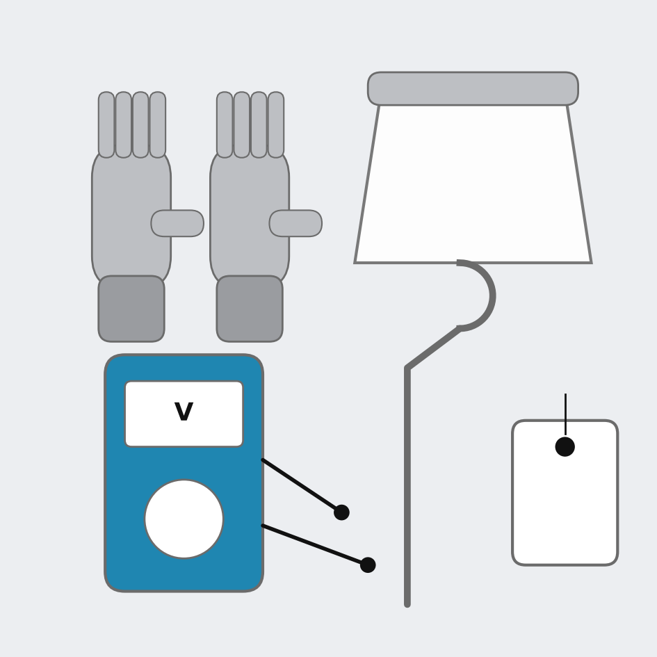 |
Do not start high-voltage work unless every item below is in place.
| Item | Requirement | Source |
|---|---|---|
| Multimeter | CAT III 1000 V or higher, DC range at least 1000 V, shrouded probes | A |
| Known voltage source | To prove the meter before and after (the truck 24 V battery is fine) | A |
| Insulating gloves | Class 0 (1500 V DC) with leather over-gloves; air-test before use | A |
| Face protection | Arc-rated face shield | A |
| Insulated tools | 1000 V rated sockets and torque wrench; any other metal tool must have an insulated handle | A, C 9.J.2 |
| Lock-out / tag-out | The NFC key card and the service disconnect (MSD) stay with the technician (the card can be handed to the safety supervisor); a sign "High-voltage work, do not energise" on the truck | A |
| Second person | Present throughout, with an insulated rescue hook | A, C 8.I |
| Diagnostic tool | To read fault codes and contactor status before power-down | A |
| Fire extinguisher | One rated for lithium battery fires must be at hand | C 8.I |
Clothing and work site (C 9.J.2)
- No metal jewellery (watches, rings, etc.) and no metal objects in work-clothes pockets (keys, metal pens, mobile phones, coins).
- Do not bring tools unrelated to the work into the work site.
- Before connecting high-voltage power, check for debris around the high-voltage equipment, tell unrelated people to keep away, and call out loudly when closing the switch.
Buddy rule (C 8.I): one person supervises, the other works. Two or more people must never work at the same time. Do not touch the person who is working.
Wear appropriate personal protective equipment before touching any high-voltage component. (B, C 8.K)
3 Power-down procedure
Source: A 4, B 1.9, C 8.K, 9.J.2
Principle (A section 1): Every way of switching the high voltage off on this truck is indirect: it opens contactors, and a contactor can weld shut. So a switch-off only means "should be dead". A measurement (chapter 4) is what proves it.
| Method | Type | How it disconnects | When it can fail |
|---|---|---|---|
| Pull the service disconnect (MSD) | Indirect | Contactor coils and the high-voltage interlock lose power; contactors open | A welded contactor does not open |
| Emergency stop, or disconnect the 24 V battery negative | Indirect | Same as above | Same as above |
| Remove a fuse or unplug a high-voltage connector | Direct | Physical break | Requires opening a cover or a connector, so it must be proven dead first |
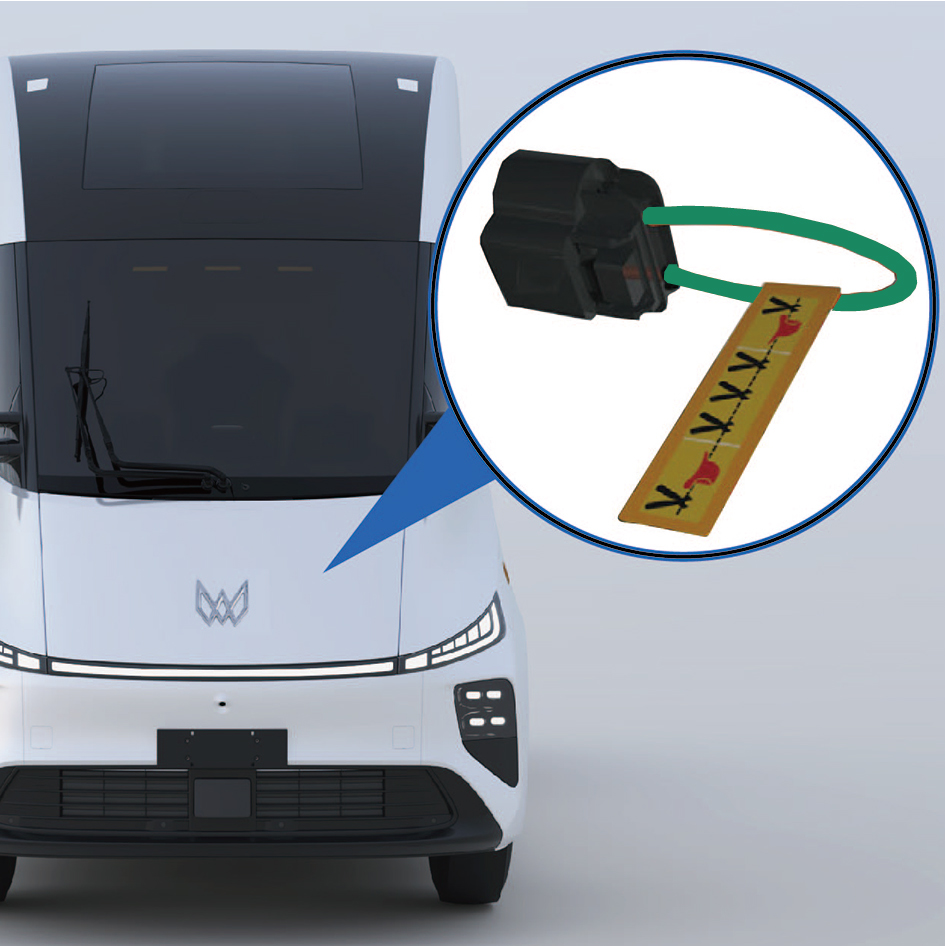
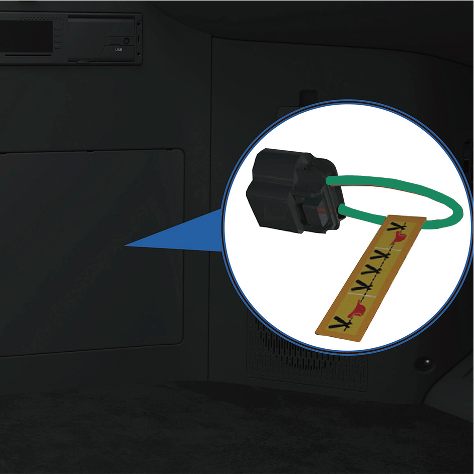
The service disconnect (MSD) is in the front compartment (under the front flip cover) or behind the trim cover at the lower left of the dashboard.
Do the steps in this order: 1) pull the service disconnect (MSD), 2) lock out and tag out, 3) disconnect the 24 V battery negative. Pull the MSD at one location only: in the cab or outside, either one. When it is out, the truck deactivates the high-voltage system automatically.
| No. | Step | Figure |
|---|---|---|
| 1 | Park and apply the EPB. Stop the truck and apply the electronic parking brake (EPB). Make sure no charging cable is connected. | 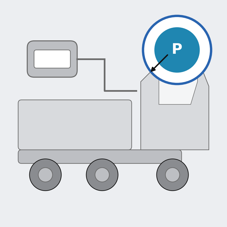 |
| 2 | Read fault codes. Connect the diagnostic tool and read the PDU fault codes. If any contactor-welded fault is present (main drive, auxiliary, heater, body-builder or fast-charge contactor), stop and see the table "If something is wrong" in section 5.9. | |
| 3 | Pull the service disconnect (MSD). Start timing here (step 6).
|   |
| 4 | Lock out and tag out. Keep the service disconnect (MSD) and the NFC key card on you. Hang the "High-voltage work, do not energise" sign on the truck. | 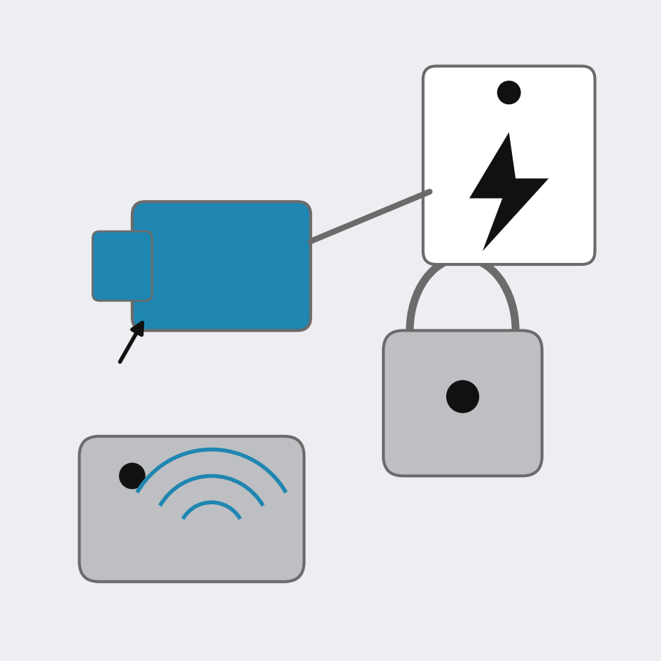 |
| 5 | Disconnect the 24 V battery negative. High voltage is powered down first (steps 3 and 4), then the battery negative. (Service manual 7.4 repeats this: power down the high-voltage system before disconnecting the battery negative.) | 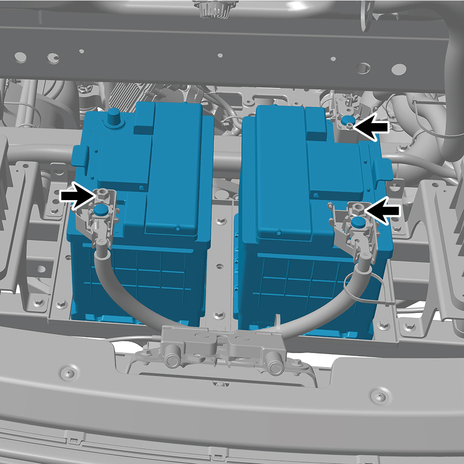 |
| 6 | Wait at least 10 minutes, counted from step 3, so the capacitors in the motor controllers and other high-voltage loads discharge. | 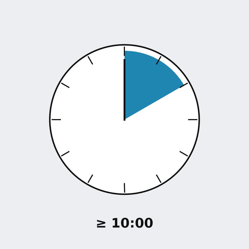 |
| 7 | Put on protective equipment: insulating gloves with over-gloves and face shield; the second person takes position. (A: required from this step on.) | |
| 8 | Prove dead, see chapter 4. Start work only when all three readings are below 60 V. | 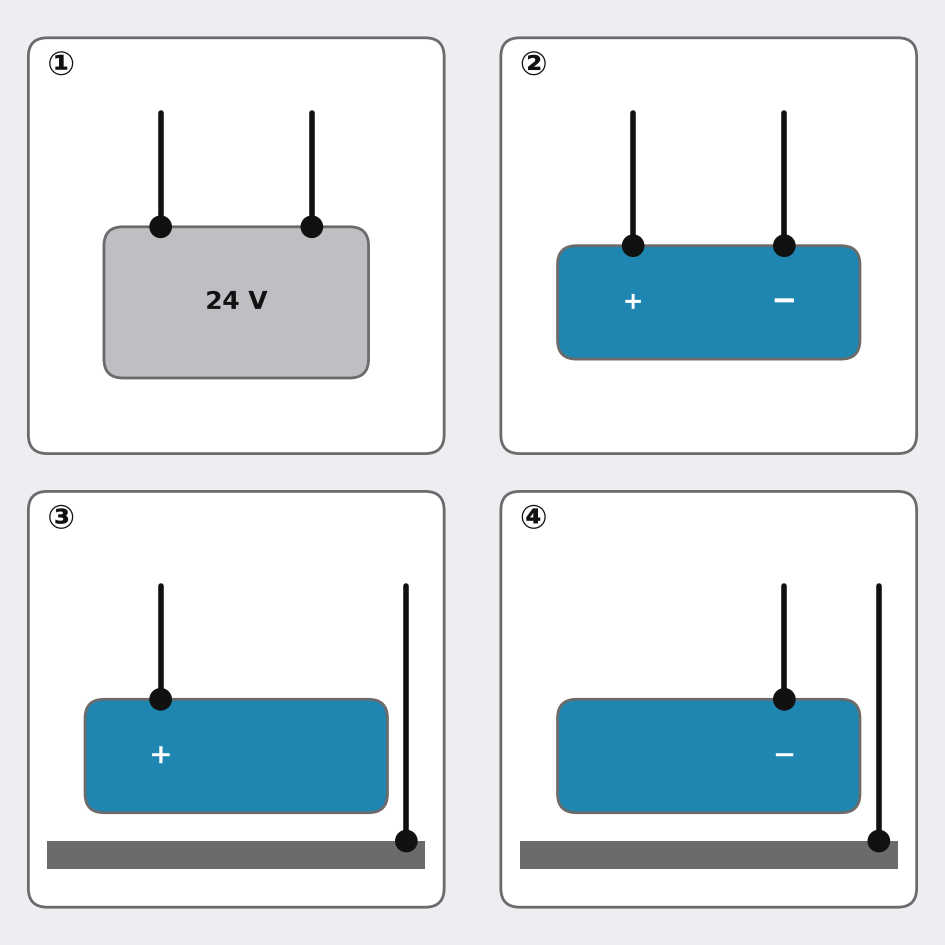 |
Warnings (B 1.9, for both locations)
- Wear appropriate personal protective equipment when touching any high-voltage component.
- Even after the high-voltage system is deactivated, do not touch high-voltage battery components. If you must work on them, wear appropriate personal protective equipment.
- If any high-voltage component is damaged, wrap the damaged part with insulating tape (then prove dead).
4 Proving dead (voltage check)
Source: A 1, A 5
|
Safe limit: below 60 V DC (A cites the DC limit of UN ECE R100 and GB 18384). After a correct power-down the reading is close to 0 V.
Why three readings, not one: the system floats (IT system): neither HV+ nor HV− is connected to the chassis. If one contactor is open, the other welded and the insulation damaged, HV+ to HV− can read 0 V while one pole is several hundred volts above the chassis.
Method: "live-dead-live" (the meter is proven before and after). Measure at the high-voltage connector of the part you will work on (zone B), in this order:
| Step | Measure | Expected | If not |
|---|---|---|---|
| ① Prove meter | 24 V battery terminals | 24–28 V | Meter or probes faulty: replace |
| ② HV+ to HV− | At the connector of the part | below 60 V (≈ 0 V) | Contactor still closed or capacitors not discharged: stop, see 5.9 |
| ③ HV+ to chassis | HV+ to a chassis ground point | below 60 V | Insulation fault or one contactor welded: stop |
| ④ HV− to chassis | HV− to a chassis ground point | below 60 V | Same as ③ |
| ⑤ Prove meter again | Back on the 24 V battery | 24–28 V | Meter failed during the test: earlier zeros are void, repeat with another meter |
Timing: wait at least 10 minutes after pulling the MSD, then measure. The 10 minutes cover the worst case: active discharge failed and the passive resistors do the work.
What stays live, what goes dead (A section 2)
- Zone A: battery packs to the PDU inputs: always live. This run has no switch in it. No power-down step makes it 0 V.
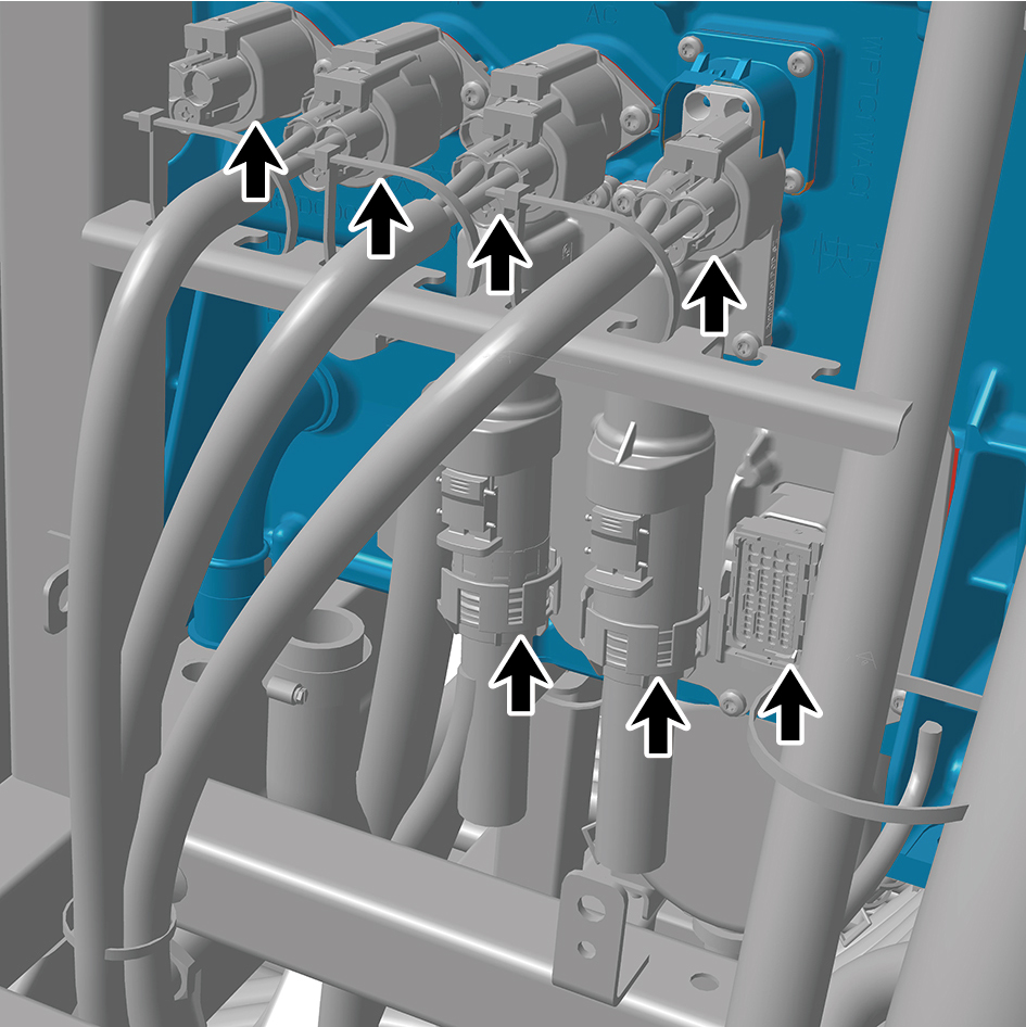
- Zone B: everything after the PDU contactors: below 60 V after power-down and a 10-minute wait.
- Readings in zone A differ: pack HV+ to HV− (cable removed) at pack voltage is normal and is measured for diagnosis only. Pack HV+ or HV− to chassis near 0 V or drifting is normal for a floating system; a steady reading near pack voltage means an insulation fault.
 |  |  |
| Version | Battery packs | Cells per pack | Pack voltage nominal / operating (A) |
|---|---|---|---|
| LFP | 4 packs: 1 left upper, 2 left lower, 3 right upper, 4 right lower | 238 | 766.4 V / 595–868.7 V |
| NCM | 6 packs: 1 left upper, 2 left middle, 3 left lower, 4 right upper, 5 right middle, 6 right lower | 204 | 754.8 V / 571.2–887.4 V |
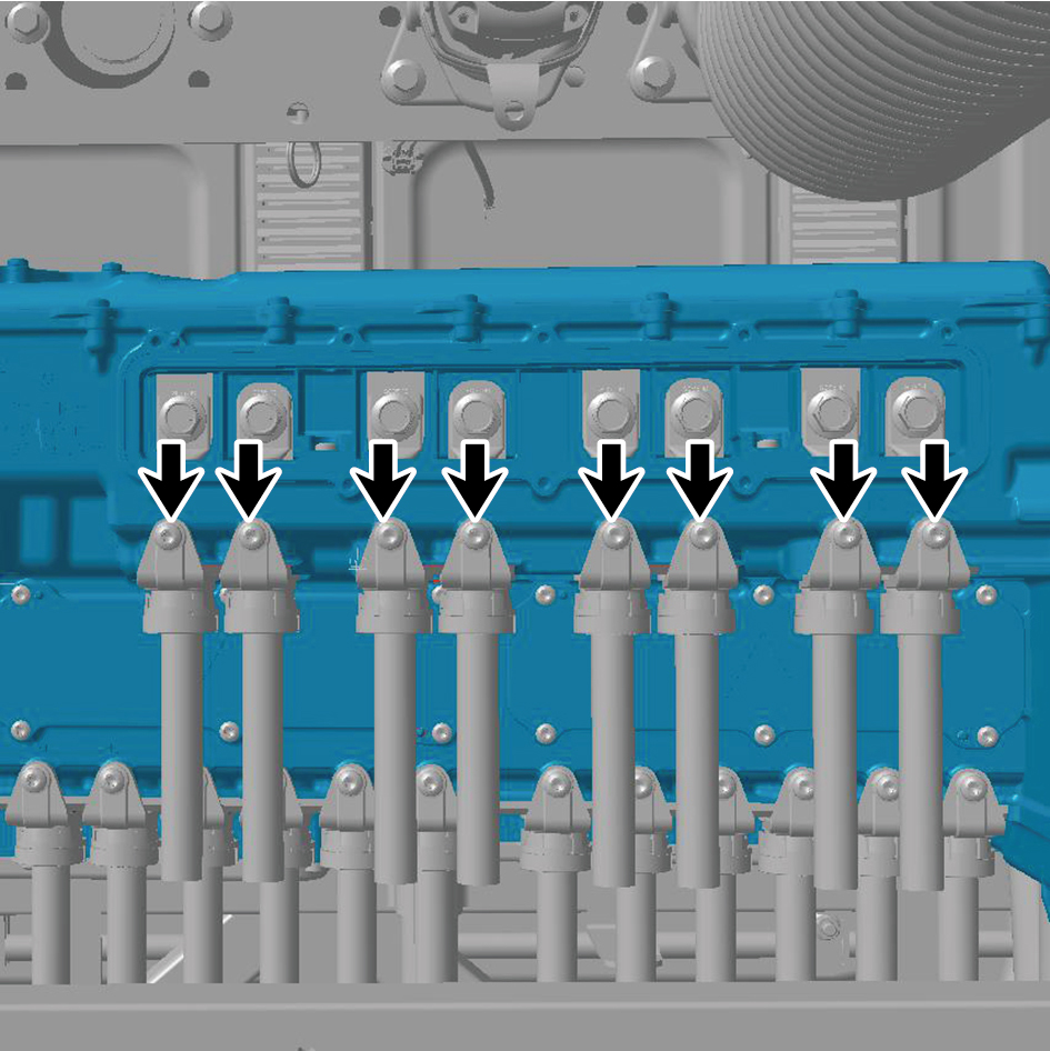
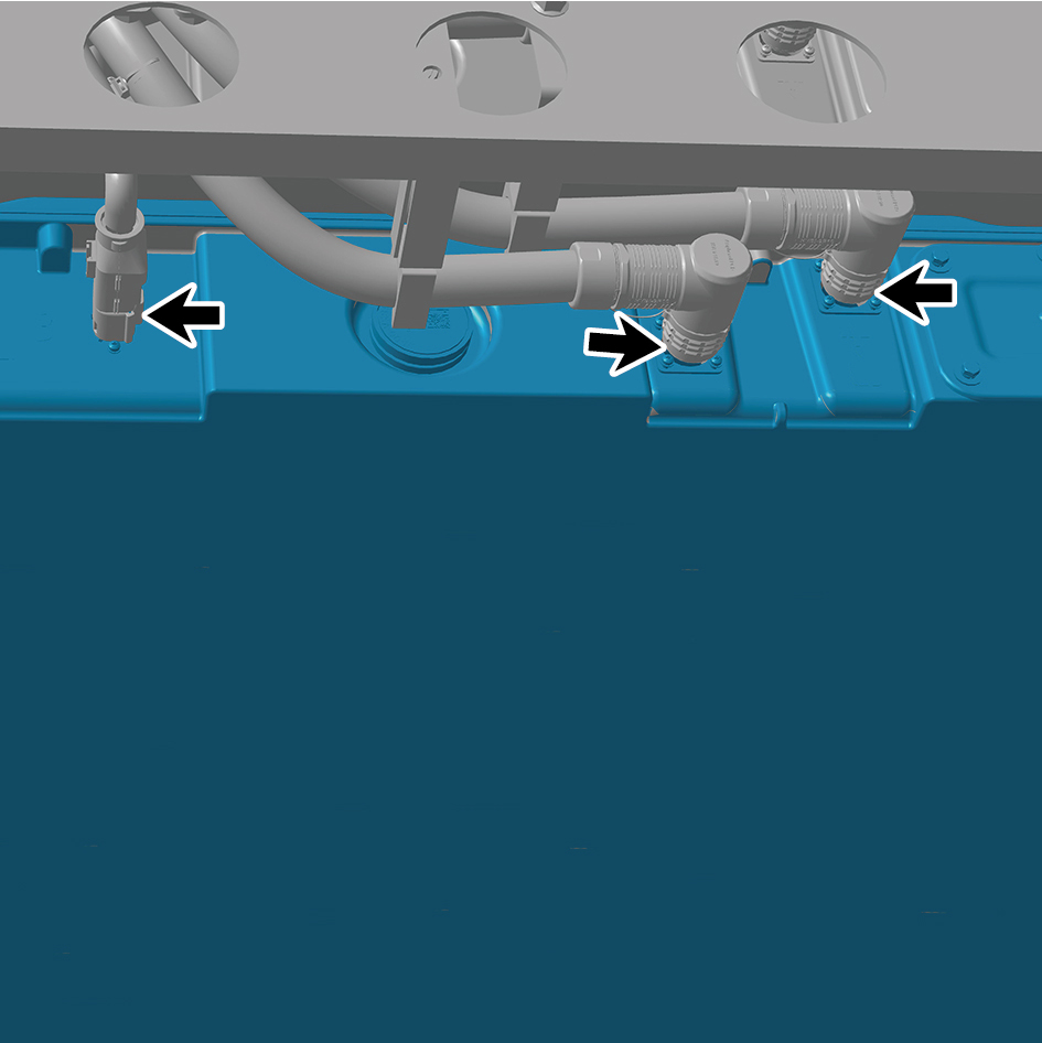
The PDU sits on the frame centreline, just behind the cab and in front of the mid axle. Each pack has one small low-voltage connector and two round high-voltage connectors (HV+, HV−) on its top edge; go by the + / − marking on the connector itself. Under the PDU is one row of 12 vertical plugs, the positive and negative of inputs B1–B6.
5 Rules while working
Source: A, C 9.J.2, D 3/5
| | |
- Orange cables are live until proven dead. After power-down, treat all orange-insulated high-voltage cables and components as live until the voltage check proves otherwise. (D, C 9.J.2)
- Never cut and never open high-voltage components or cables. (D) Never open a battery pack housing. (A)
- Never unplug under load (it arcs). If a contactor is welded, that circuit is still connected to the battery: hand it to a qualified high-voltage specialist. (A)
- Lock-out / tag-out: the service disconnect (MSD) and NFC key card stay with you, and the "do not energise" sign stays on the truck until the work is finished. (A)
- When repairing high-voltage electrical parts, follow the fixed order of chapter 3: first pull the service disconnect (MSD), then lock out and tag out, then disconnect the 24 V battery negative; wait 10 minutes and prove dead before you start (chapters 3 and 4). No cutting of anything in service or maintenance work. Always power down with the service disconnect (MSD). (A, C 9.J.2)
- The second person is present throughout and does not touch the person working. (A, C 8.I)
- No metal jewellery, no unrelated metal objects, only tools with insulated handles. (C 9.J.2)
- Damaged high-voltage cable: wrap the damage with insulating tape, then prove dead. (A, B, C 8.K)
- If something is wrong (A section 6): first stop work and step away from live parts.
| Situation | Action |
|---|---|
| HV+ to HV− still above 60 V after 10 minutes | Wait another 10 minutes and measure again. If it does not fall, a contactor has not opened: treat it as welded. |
| Contactor-welded fault code, or HV+ to HV− steady at pack voltage | That circuit is still connected to the battery. Do not unplug under load. Escalate to a qualified high-voltage specialist. |
| One pole steady at several hundred volts to chassis | Insulation fault. Any metal on the truck may be live. Close off the area and escalate. |
| Meter check ① or ⑤ fails | Change the meter and restart at ①. Earlier readings are void. |
| Battery pack impacted, flooded, smoking, smelling or hot | No voltage check, no pack work. Move the truck to an open area, isolate it and monitor temperature. Stop any charging. |
- Long parking (C 9.J.4): if the vehicle is parked for a long time, check the high-voltage battery every two weeks and charge and maintain it regularly, to prevent leakage and loss of performance.
6 Restoring high voltage (power-up)
Sources: A section 4 last paragraph (the only service-side restore steps), C 9.J.2, C 6.D.1 (power-on and READY). B (manual 1.9) has no restore steps.
| 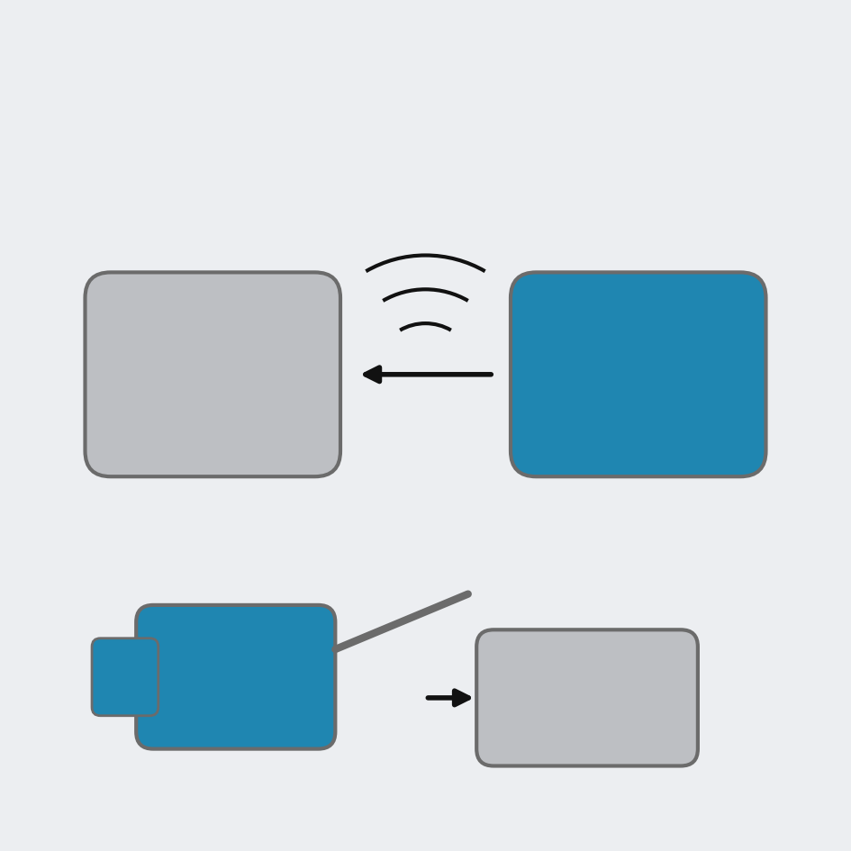 | |
| No. | Step | Figure |
|---|---|---|
| 1 | Make sure the work is finished and no debris is left around the high-voltage equipment; tell unrelated people to keep away. (C 9.J.2) | Figure 1 |
| 2 | Refit every high-voltage connector until it clicks, then tug it once. (A) | Figure 13, Figure 12 |
| 3 | Refit the service disconnect (MSD); remove the "do not energise" sign. (A) | Figure 4, Figure 5, Figure 6 |
| 4 | Connect the 24 V battery negative. (A) | Figure 7 |
| 5 | Call out loudly to people nearby when switching on. (C 9.J.2) | Figure 2 |
| 6 | After power-up read fault codes with the diagnostic tool and confirm there is no insulation fault and no interlock fault. (A) | Figure 3 |
| 7 | Power on as in Owner Manual 6.D.1: hold the NFC card to the swipe position; the vehicle runs a self-test and connects the high voltage; when the "Vehicle ready" indicator comes on the truck is READY. If it does not come on, do not swipe again (swiping while powered on switches it off); read the cluster message and, if it reports a fault, contact an authorised service centre. (C 6.D.1) | Figure 3 |
Gap: the sources give no insulation-resistance limit or test, no tightening torque or locking detail for high-voltage connectors, and no measurement step before power-up.
7 Emergency (accident, fire, submersion, towing)
Sources: D (Emergency Response / Rescue Guide WINDROSE-202408-001, Version 01, all Windrose vehicles from 2024 onward); C 8.I and 8.K as supplement.
WARNING: lack of engine noise does not mean the vehicle is off. Silent movement or instant restart capability exists until the vehicle is fully shut down. Wear appropriate PPE. (D)
7.1 Identification and stabilisation
|
- The Windrose emblem indicates a fully electric vehicle; the model name does not appear on the exterior. (D §1)
- Chock the wheels. Lift only at the marked chassis / battery-pack lift points and avoid the HV battery enclosure. (D §2)
7.2 Disabling the high voltage: First Responder Loop (D §3)
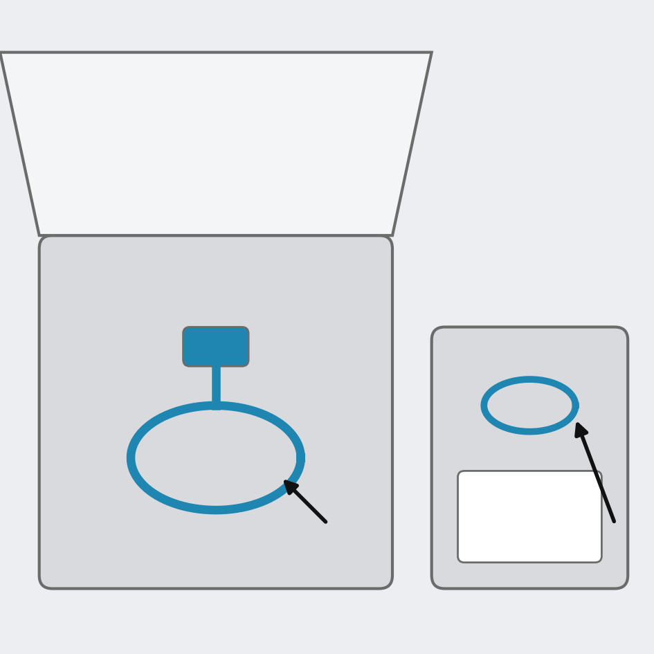 |
For first responders only, and only in an emergency when normal power-down is impossible. Never cut anything during service or maintenance: use the service disconnect (MSD) (chapter 3).
- Method A (primary): open the hood and cut the First Responder Loop.
- Method B (secondary): open the instrument panel (IP) and cut the Secondary Responder Loop.
- This cutting is for the emergency described above only. After cutting, treat all orange-insulated high-voltage cables and components as live until proven otherwise. Never cut or open high-voltage components or cables.
- The Owner Manual (8.K) also gives the cut-off from outside (pull the hood release handle twice, then pull the service disconnect (MSD) in the engine compartment) and from inside (trim cover at the lower left of the instrument panel, then pull the service disconnect (MSD)). In an emergency (first responders only) the operator can cut the orange harness on the service disconnect (MSD) to prevent it being energised again and let the vehicle deactivate the high voltage automatically. In a collision the high-voltage system deactivates automatically. (C 8.K)
- After an accident: do not touch orange high-voltage cables or parts in contact with them. Electrical and mechanical releases may fail; doors may not unlock from outside (extrication may be needed); seats are pneumatic and the steering wheel is electric and may not work. (D §4, C 9.J.2)
7.3 Protective equipment for rescue personnel (C 8.I)
|
Impact-rated safety goggles; Class 0 (1,000 V rated) insulating gloves; insulated tools for high-voltage work; insulating rescue hooks; a fire extinguisher rated for lithium battery fires; buddy system; remove all metal jewellery.
7.4 Stored energy and hazards (D §5)
|
| Item | Requirement |
|---|---|
| 12 / 24 V system | Conventional low-voltage battery: disconnect as usual |
| 800 V traction battery | Lithium-ion (LFP). Cells are sealed: not enough electrolyte to form a pool |
| HV cables | Orange insulation; never cut or open |
| Coolant | Orange, non-conductive; loop for the HV battery and power electronics |
| Air springs / preloaded springs | Pneumatic stored energy: release per OEM procedure |
| Seat-belt pre-tensioners | Pyrotechnic: deploy once on impact; do not cut after deployment |
7.5 Fire (D §6)
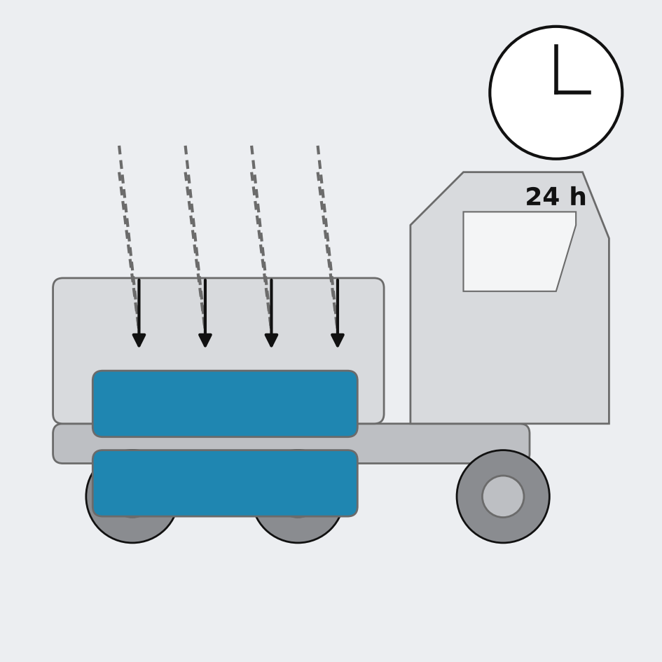 |
- Do NOT submerge the vehicle to extinguish or cool the battery fire.
- Use large amounts of water to cool the battery enclosure.
- Monitor the HV battery temperature for at least 24 hours.
- Possible battery re-ignition: secure the area.
7.6 Submersion (D §7)
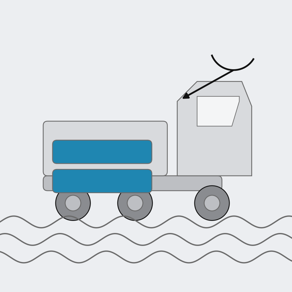 |
Treat a submerged Windrose like any other submerged vehicle. Wear appropriate PPE for water rescue. Remove the vehicle from the water and continue with normal high-voltage disabling. Any submerged vehicle, including non-Windrose vehicles, could pose a fire risk, especially in salt water. Tilt the vehicle to the side to let water drain out and store it flat.
7.7 Towing / transportation / storage (D §8 and towing guide)
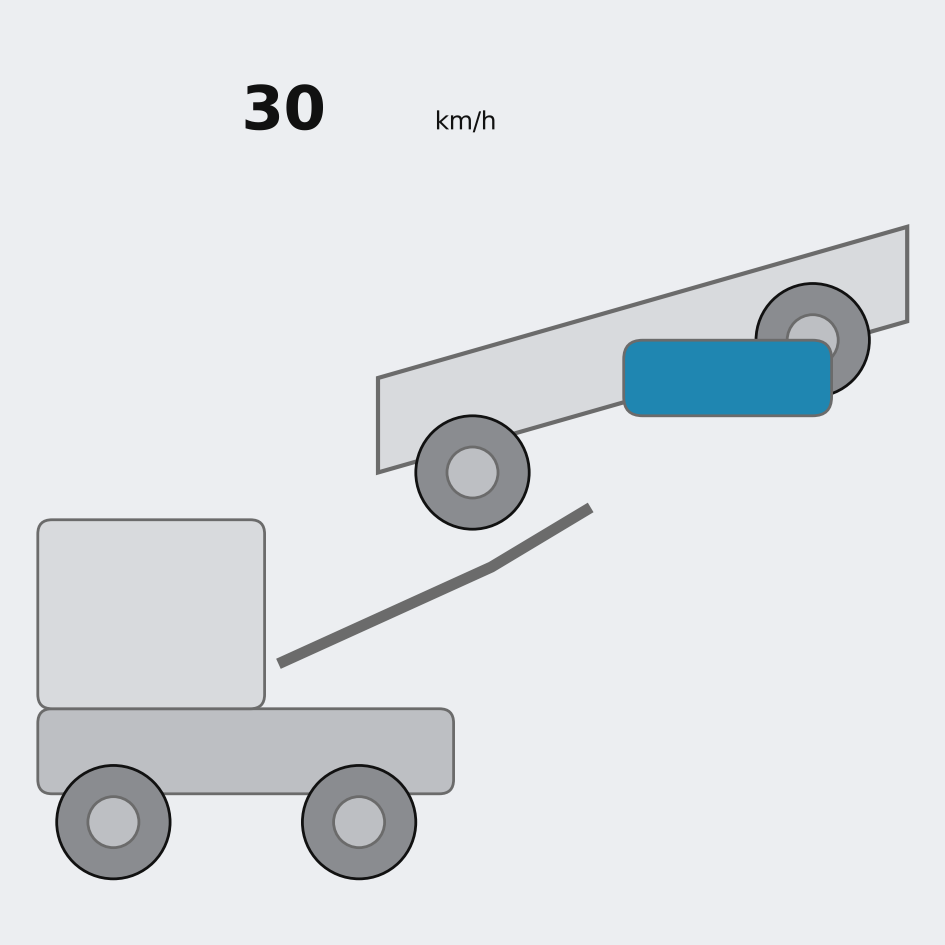 |
- Front towing only. Rear towing is not an option: it damages the air springs and other components, and the bumper.
- Check the HV battery temperature before transport. If there is abnormal battery temperature, smoke, fire history, battery impact or fluid leakage, do not treat it as a routine case: escalate before loading (Windrose transport escalation criteria).
- Do not use the recovery method if battery damage, abnormal battery temperature, smoke, fire, fluid leakage or water submersion is suspected. Follow the transport / storage escalation process.
- General towing requirements: parking brake released, doors closed, gear selector in Neutral (N), e-axle differential lock locked mechanically, both left and right drive shafts removed.
- Method 1 (front towing without drive shafts): locate the differential-lock switch on the e-axle and remove it; install the M18 × 1.5 bolt (L = 40 mm) into the differential lock until it is blocked; remove all bolts of the drive shafts and both drive shafts; cover the hub ends with metal plates or plywood to keep lubricant in and contaminants out; maximum speed 30 km/h (19 mph) (three or four motors, same procedure); extend the stinger, place the lift adaptor under the tyres and secure the tyres to the tow-truck crossbar with chain or ratchet strap.
- Recovery method (drive shafts mounted, Neutral (N) illuminated): maximum speed 15 km/h (9 mph).
- Storage after a fire: store outside, at least 15 m (50 ft) from other vehicles and structures. A vehicle involved in a fire must not be treated as a routine towing or storage case until battery risk has been assessed.
Contacts (D): 24/7 roadside assistance +1 (586) 604 5918; first-responder safety firstrespondingsafety@windrose.tech; information portal windrose.tech.
Figures used
| # | Figure | Source |
|---|---|---|
| 1 | High-voltage layout (schematic): battery packs and PDU in blue | Windrose redraw, pending Wen review |
| 2 | Protective equipment and tools: meter, insulating gloves, face shield, rescue hook, tag | Windrose redraw, pending Wen review |
| 3 | EPB applied (P) and diagnostic tool connected | Windrose redraw, pending Wen review |
| 4 | Service disconnect (MSD) in the front compartment, after the front flip cover is open (manual 1.9.1.2) | WH13 1.9 · p29_0 · blue highlight, manual figure |
| 5 | Service disconnect (MSD) behind the trim cover at the lower left of the dashboard (manual 1.9.1.1) | WH13 1.9 · p29_1 · blue highlight, manual figure |
| 6 | Lock-out / tag-out: service disconnect (MSD), padlock, NFC key card, "do not energise" tag | Windrose redraw, pending Wen review |
| 7 | 24 V batteries in the front compartment, terminals and negative cable (manual 7.4) | WH13 7.4 · p1286_9 · blue highlight, manual figure |
| 8 | Wait at least 10 minutes | Windrose redraw, pending Wen review |
| 9 | Prove dead, live-dead-live: ① 24 V battery, ② HV+ to HV−, ③ HV+ to chassis, ④ HV− to chassis, (⑤ 24 V battery again) | Windrose redraw, pending Wen review |
| 10 | PDU: row of battery input plugs under the PDU (manual 4.6) | WH13 4.6 · p354_2 · blue highlight, manual figure |
| 11 | Battery pack: connectors on the top edge, NCM pack shown (manual 4.3) | WH13 4.3 · p248_10 · blue highlight, manual figure |
| 12 | PDU: high-voltage harness connectors, zone B (manual 4.6) | WH13 4.6 · p360_21 · blue highlight, manual figure |
| 13 | Refit: insert until it clicks; refit the service disconnect (MSD) | Windrose redraw, pending Wen review |
| 14 | First Responder Loop in the front compartment and Secondary Responder Loop at the instrument panel (schematic; position not to scale) | Windrose redraw, pending Wen review |
| 15 | Fire: cool the battery enclosure with large amounts of water, monitor 24 h | Windrose redraw, pending Wen review |
| 16 | Submersion: remove from the water, tilt the vehicle to drain | Windrose redraw, pending Wen review |
| 17 | Front towing, e-axle area; maximum 30 km/h without drive shafts; never rear-tow | Windrose redraw, pending Wen review |